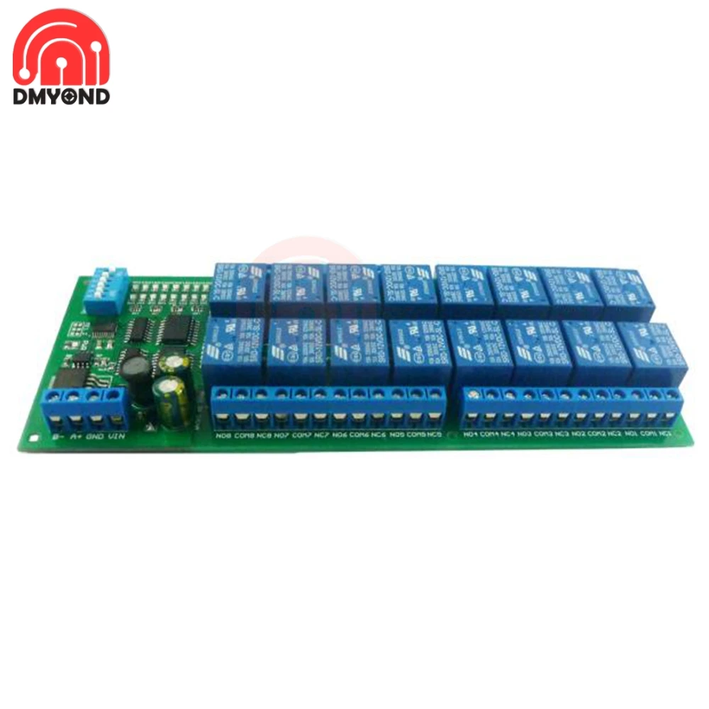
Modbus RTU 12V 10A 16 Channel DIN Rail Box PLC Expansion Board RS485 Relay Module Modbus RTU Relay RTU Protocol Remote Smart Control

Description:
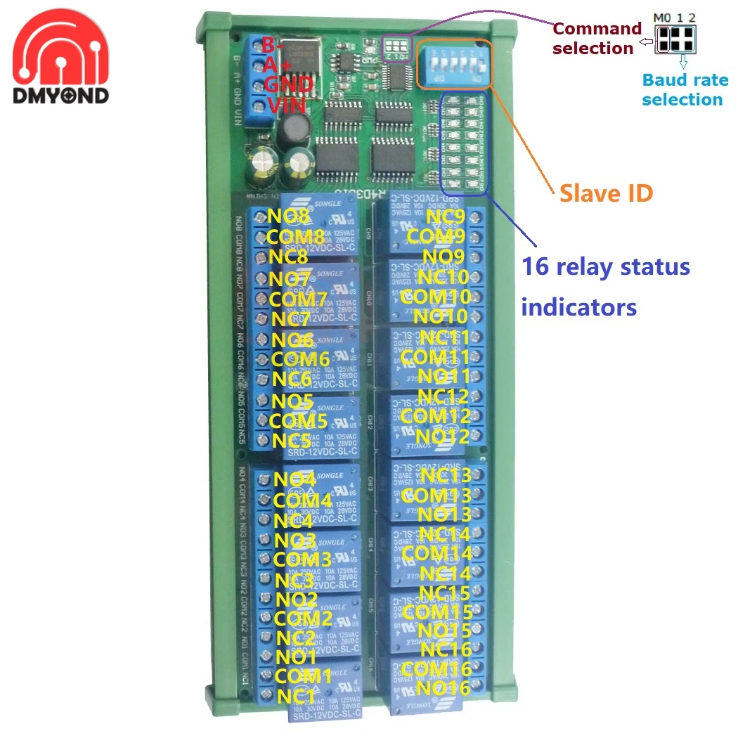
16ChannelRailRS485 Relay Manual
Features:
1: DC 12V power supply
2: Standby current (all relays closed) 13MA, 1 relay open 41MA, 2 relays open69MA, 3 relays open95MA,4 relays open 122MA,5 relays open 148MA,6 relays open 174MA, 7 relays open 198MA,8 relays open 225MA.etc
3: "open" "close" "Momentary" "Self-locking" "Interlock" "Delay" 6 Commands
4: Two instruction-control mode :MODBUS RTUcommand andATcommand
5: Under the "Delay" command ,the maximum delay is 255 seconds;
Under the AT command ,the maximum delay is 9999 seconds
6 MODBUS commands can be made serial HyperTerminal (serial assistant)OR"Modbus Poll"Enter; AT commands can be made serial HyperTerminal (serial assistant) Enter;
7 Under the MODBUS command mode, it can support up to 64 devices in parallel
8The default baud rate is 9600BPS. The baud rate can be selected through jumpers: 2400 4800 9600 19200BPS
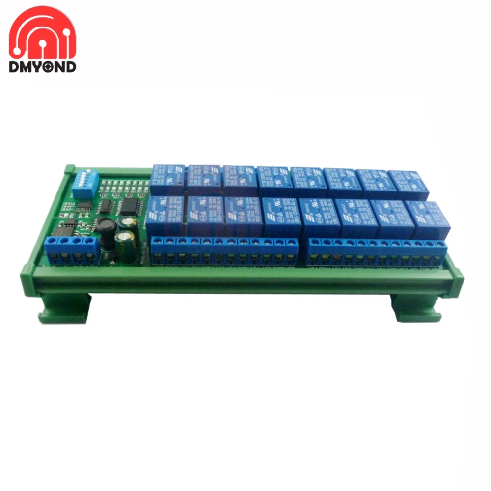
9Size: 180 * 72 * 20mm(Only PCB Board);184* 88* 42mm(with Din Rail Box)
10Weight:230g(Only PCB Board);358g(with Din Rail Box)
11Maximum load: 10A / 250VAC, 10A / 125VAC, 10A / 30VDC, 10A / 28VDC, 10A / 12VDC
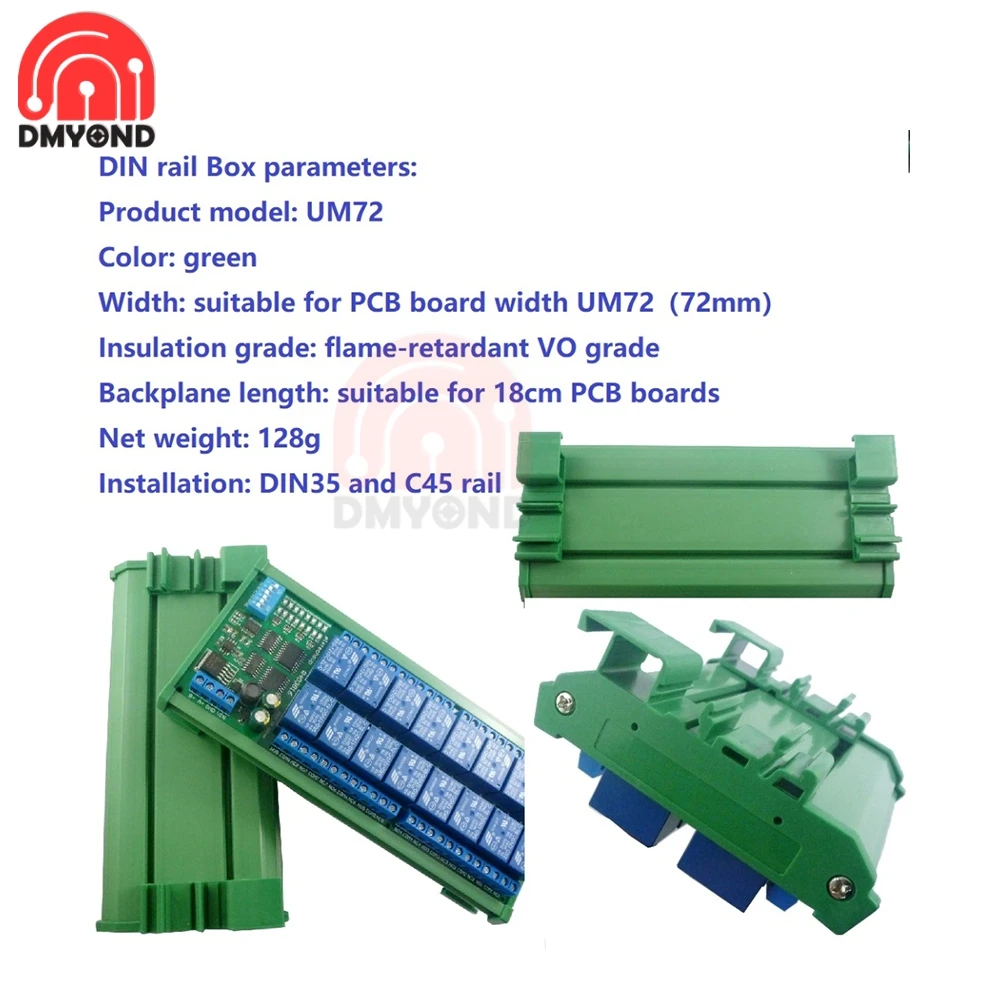
DIN rail Box parameters:
Product model: UM72
Color: green
Width: suitable for PCB board width UM72(72mm)
Insulation grade: flame-retardant VO grade
Backplane length: suitable for 180mm PCB boards
Net weight:128g
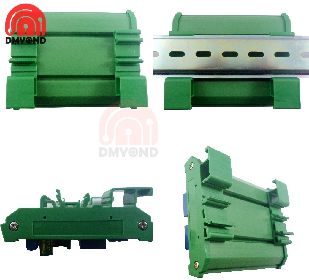
Installation: DIN35 and C45 rail
Glossary:
NO : Relay normally open contact
COM : Relay common contact
NC : Relay normally closed contact
Open : NO connection COM, NC disconnect COM
Close : NO disconnect COM, NC connection COM
Momentary : Enter the Momentary command, the RreceiverRelay is Open, delay of 0.5 seconds after,Relay is Close;
Toggle : Enter the Toggle command, the RreceiverRelay is Open, Enter the Toggle commandagain,Relay is Close;
Latched : Enter the Channel 1 Latched command, the receiver Channel 1 is Open, the Channel 2 is Close.
Enter the Channel 2 Latched command the receiver Channel 2 is Open, the Channel 1 is Close.
Enter the Channel 3 Latched command the receiver Channel 1 is Close, the Channel 2 is Close.
Delay : Enter the Delay command, the RreceiverRelay is Open, delay of0-9999seconds(MODBUScommand is 0-255 seconds )after,Relay is Close;
During the delay, Eter theClosecommand, immediately close the relay
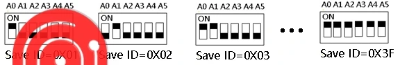
SlaveID: A0-A5 is the slaveID, you can choose 64 different slaveID.
Under the MODBUS command mode,the slave ID must be correct
1This version has 2 Command modes, MODBUS RTU Command and AT Command.2The default Command is the MODBUS RTU Command, compatible with older versions.
3Switch to AT command by shorting the M0 pad.
4The default baud rate is 9600BPS. You can also select the baud rate by shorting the M1 and M2 pads.

|

|

|

|
9600BPS(default) |
2400BPS |
4800BPS |
19200BPS |
command Description, Please refer to"16Channel Rail RS485 Relay commamd"
Typical applications:
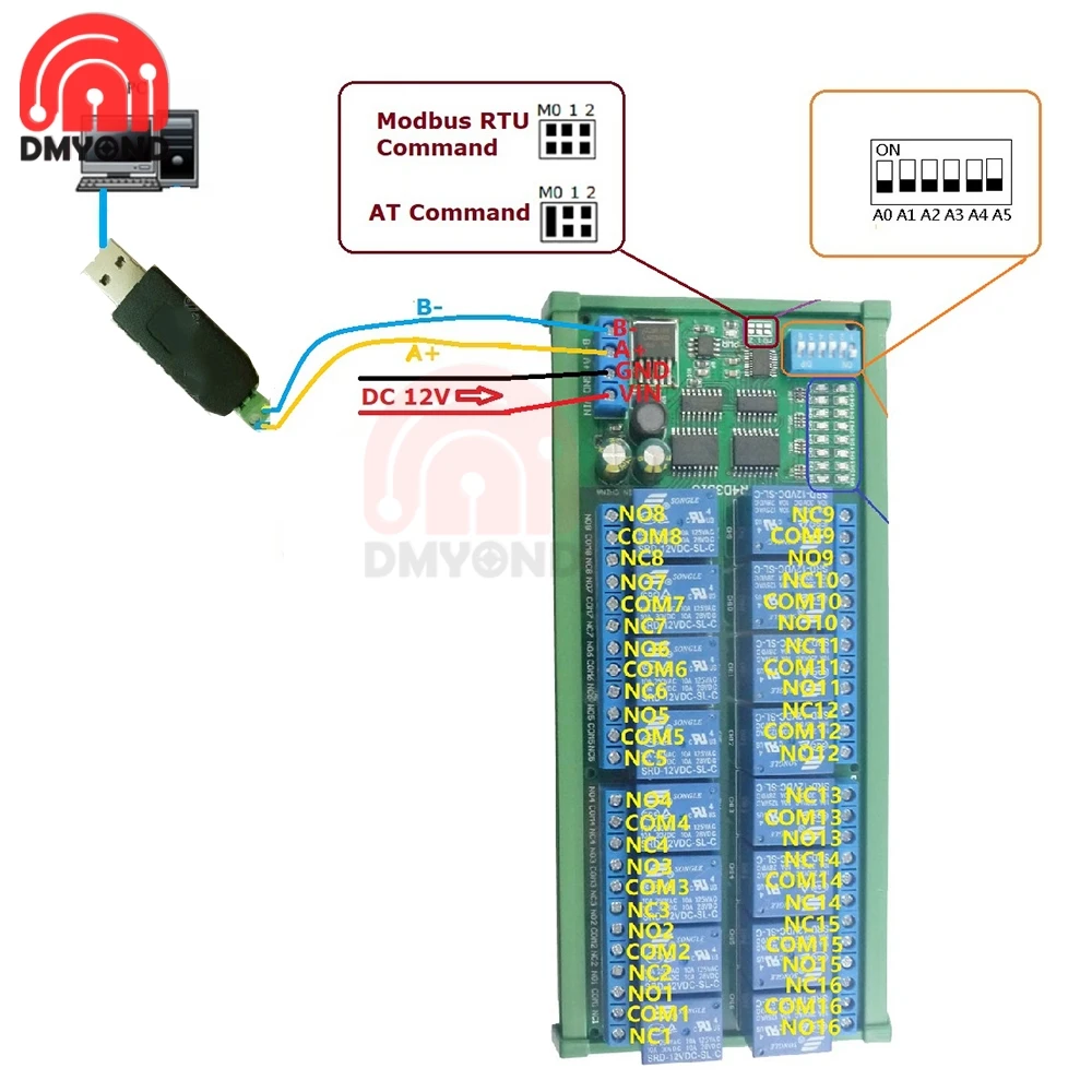
1 When controlling a module, you can use the MODUBS RTU instruction or the AT instruction. In AT command mode, the dial switch (slave address) is invalid and can only control one module at a time.
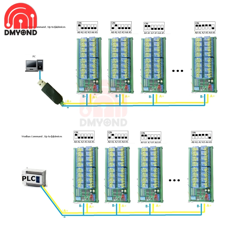
MODBUS command mode (HEX), you can control a variety of ways: Serial Hyper Terminal Control (need to manually add the CRC), Modbus Poll software control (software automatically add the CRC), PLC or MCU process control
Wiring Diagram:
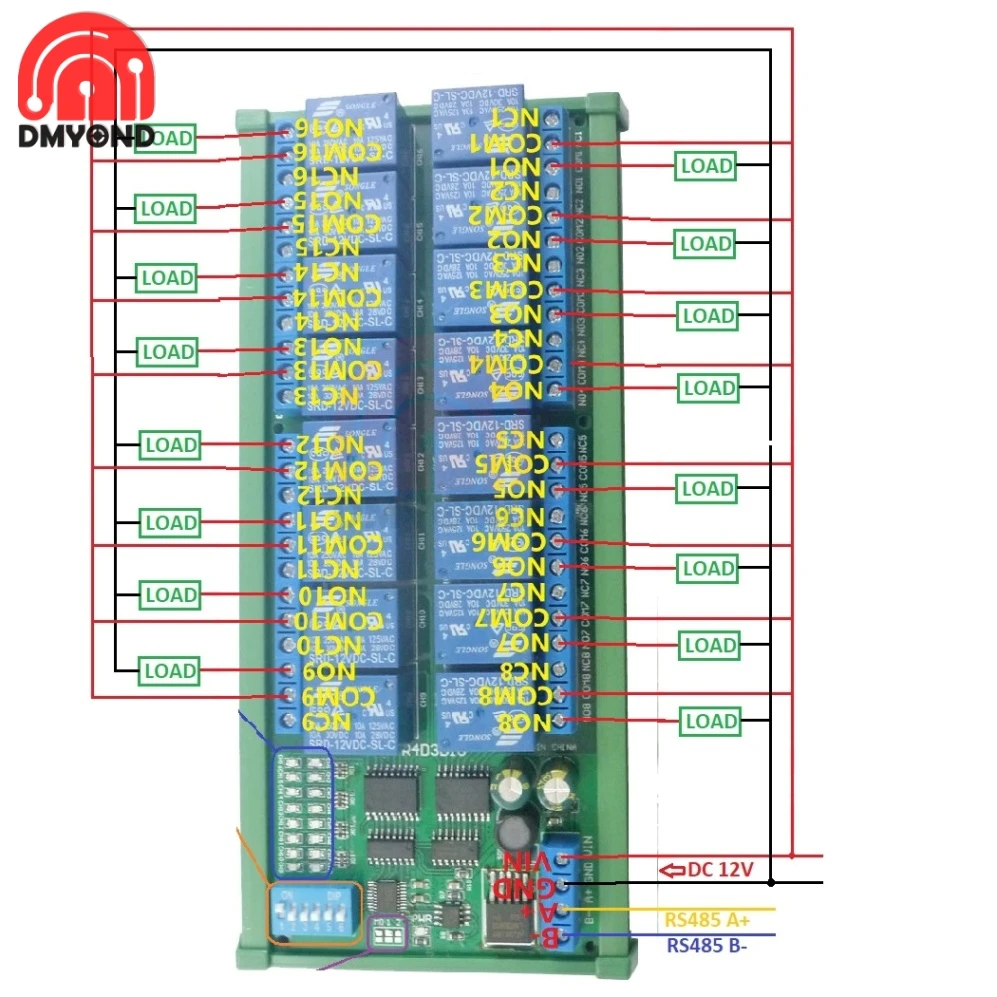
1DC 12V control circuit,Wiring diagram below. "LOAD" may be camera,LED lights, fans, motors and other DC 12V equipment
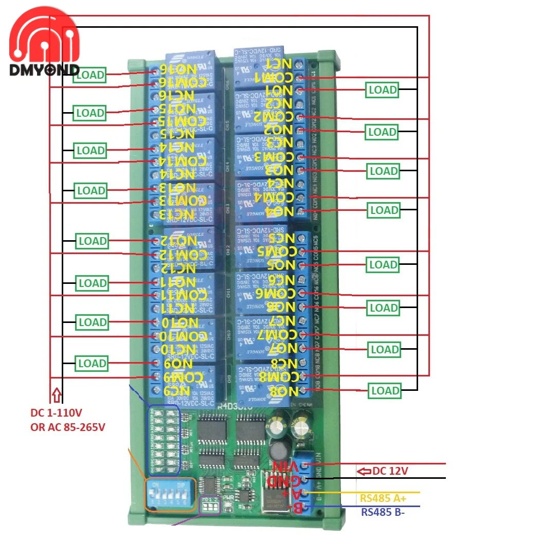
2 DC 1-110VAC 85-265V control circuit,Wiring diagram below(Note:If not DC 12V load, need another DC 12V power supply). "LOAD" may be LED lights, fans, motors Lights, fluorescent lights, solar water heaters and other DC AC equipment


 배송기간
배송기간