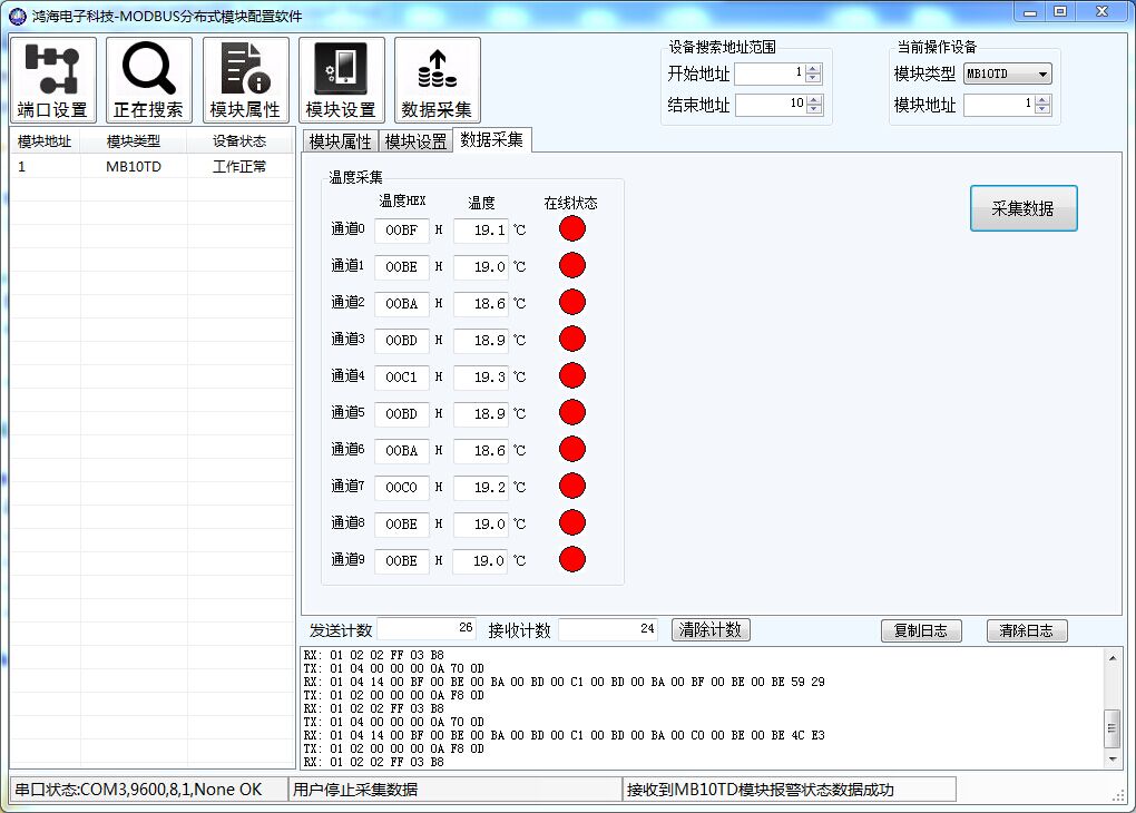
MB10TD 10-channel DS18B20 temperature and humidity acquisition block software acquisition interface
Chapter 1 Product Introduction
I. Overview
MB10TD 10-channel DS18B20 temperature acquisition module can collect 10-channel Dallas semiconductor temperature sensor DS18B20, which has high temperature accuracy and good consistency; The temperature signal data collected by the module is output through RS485 interface. Module adopts Modbus-RTU communication, which can be adapted to PLC, man-machine screen, DCS and various configuration software, etc.
The module can update the on-line status of sensors in real time and monitor the on-line status of 10 external DS18B20 sensors in real time by querying the corresponding register status
It can be used for temperature data collection of cold storage, environmental monitoring of vegetable greenhouse, animal breeding industry, temperature monitoring of granary, egg hatching, medicine refrigeration, various environmental temperature data collection and control, etc.
II. Characteristics
1. The high-speed parallel acquisition temperature sensor DS18B20 has good real-time performance for temperature monitoring
2. Real-time monitoring the on-line status of sensor DS18B20 is convenient for users to deal with problems and locate fault positions on site
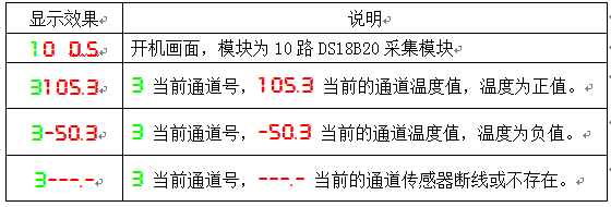
3. 5-digit digital tube display alternately displays the real-time temperature value of each channel, which is convenient for on-site viewing of real-time temperature
4. The standard Modbus-RTU protocol can be adapted to PLC, human-machine screen, DCS and various configuration software
5. Communication protection: The isolated RS485 communication signal output interface adopts over-voltage and over-current double protection
6. Power polarity protection
III. Technical indicators

IV. Appearance of products

V. Function description of module indicator light and switch
1. POW/SET; Module working status indication
A. The green light is on: the module is working in the running state B. The red light is on: the module has configuration parameters written and needs to be powered on again
2. TXD/RXD: Communication status indication
A. Green light flashes: Communication receives data B. Red light flashes: Module is sending data
C. Green light is always on: the communication RS485 line connected to DATA + and DATA-is connected backwards or the connection is broken
3. Reset switch in upper left corner of module
A. When the communication parameters (module address baud rate check bit) are unknown or the communication parameters are mistakenly set and the module communication cannot be established, the solution is to reset the communication parameters; We press and hold the reset switch with a paper clip and do not release it for 5 seconds. After the module [POW/SET] red indicator lights up, the reset switch is released at this time, the communication parameters have been reset. Just turn off the power supply of the module and restart it once. At this time, the communication parameters of the module have been reset
B. Communication parameters after reset: Address: 1baud rate: 9600bps parity bit: None
4. Digital tube display instructions
VI. Typical application wiring diagram

VII. Terminal Definition

VIII. Principle block diagram

Chapter 2 Modbus Register and Communication Protocol Description
I. MODBUS function code and address range supported by module
 II. Register definition description
1. Input Register (0x02H)
address |
parameter |
Read/Write
|
minimum value
|
Maximum |
explain |
10001 |
DI0 |
read-only
|
0 |
1 |
Channel 0 DS18B20 online status
|
10002 |
DI1 |
read-only
|
0 |
1 |
Channel 1 DS18B20 online status
|
10003 |
DI2 |
read-only
|
0 |
1 |
Channel 2 DS18B20 online status
|
10004 |
DI3 |
read-only
|
0 |
1 |
Channel 3 DS18B20 online status
|
10005 |
DI4 |
read-only
|
0 |
1 |
Channel 4 DS18B20 online status
|
10006 |
DI5 |
read-only
|
0 |
1 |
Channel 5 DS18B20 online status
|
10007 |
DI6 |
read-only
|
0 |
1 |
Channel 6 DS18B20 online status
|
10008 |
DI7 |
read-only
|
0 |
1 |
Channel 7 DS18B20 online status
|
10009 |
DI8 |
read-only
|
0 |
1 |
Channel 8 DS18B20 online status
|
10010 |
DI9 |
read-only
|
0 |
1 |
Channel 9 DS18B20 online status
|
2. Input register (function code: 0x04H)
address |
parameter
|
Read/Write
|
minimum value
|
Maximum |
explain |
30001 |
Channel 0 DS18B20 temperature
|
read-only
|
-55.0 |
125 |
Temperature value
0.1℃/bit |
30002 |
Channel 1 DS18B20 temperature
|
read-only
|
-55.0 |
125 |
Temperature value
0.1℃/bit |
30003 |
Channel 2 DS18B20 temperature
|
read-only
|
-55.0 |
125 |
Temperature value
0.1℃/bit |
30004 |
Channel 3 DS18B20 temperature
|
read-only
|
-55.0 |
125 |
Temperature value
0.1℃/bit |
30005 |
Channel 4 DS18B20 temperature
|
read-only
|
-55.0 |
125 |
Temperature value
0.1℃/bit |
30006 |
Channel 5 DS18B20 temperature
|
read-only
|
-55.0 |
125 |
Temperature value
0.1℃/bit |
30007 |
Channel 6 DS18B20 temperature
|
read-only
|
-55.0 |
125 |
Temperature value
0.1℃/bit |
30008 |
Channel 7 DS18B20 temperature
|
read-only
|
-55.0 |
125 |
Temperature value
0.1℃/bit |
30009 |
Channel 8 DS18B20 temperature
|
read-only
|
-55.0 |
125 |
Temperature value
0.1℃/bit |
30010 |
Channel 9 DS18B20 temperature
|
read-only
|
-55.0 |
125 |
Temperature value
0.1℃/bit |
3. Hold register (function code: 0x03H0x06H0x10H)
 III. Calculation method of converting temperature and humidity sampling values (30001-30004) into actual data
1. Calculation instructions

2. Calculating examples
If the number read by channel 0 (30001) is 1234, the actual temperature of channel 0 is 1234/10 = 123.4 ℃
IV. Modbus RTU Communication Example
Example of reading 10 channels of temperature data (module address: 1)
TX: 01 04 00 00 00 0A 70 0D
RX: 01 04 14 00 BD 00 BC 00 B9 00 BC 00 BF 00 BB 00 BA 00 BF 00 BB 00 BE 65 F9
Chapter III Product Configuration
I. Communication settings
1. Default factory communication parameters

2. Reset communication parameters
1) Why reset communication parameters:
A) The user forgot the communication parameter setting and could not communicate with the module
B) The user has set the communication parameters incorrectly and cannot communicate with the module
2) How to reset communication parameters
A) Press and hold the touch switch on the right side of the module for more than 5 seconds until the red indicator light "POW/SET" of the module lights up, and then release the pressed touch switch
B) The communication parameters have been reset to the default value after the module is powered on again after the power is cut off
3. Setting up communication parameters example
A. Current Communication Parameters: Address: 1baud Rate: 9600bps Parity Bit None
B. Communication parameters to be set: Address: 2baud rate: 19200bps parity bit none
C. Organize the written commands. Organize the commands with 0x10 function code
project
|
Number of bytes
|
data
|
address |
1 |
0x01 |
Function code
|
1 |
0x10 |
Start address
|
2 |
0x0046 |
Number of registers
|
2 |
0x0003 |
Number of bytes
|
1 |
0x06 |
Data 1
|
2 |
0x0002 |
Data 2 |
2 |
0x0004 |
Data 3
|
2 |
0x0000 |
CRC check
|
2 |
0x3C4A |
D. Organized Send Instructions: 01 10 00 46 00 03 06 00 02 00 04 00 00 3C 4A


 배송기간
배송기간